

Robot Connector Supplier Guide for Choosing Durable Automation Components
2026-11-17
Industrial automation rarely forgives a weak link. Every connector in the chain must withstand vibration, thermal cycling, moisture, and the daily grind of high-motion operations. Yet many component guides skip the details that actually determine service life. This guide from REUNION takes a different approach: it focuses on the material, contact design, and sealing choices that keep your equipment running when the environment pushes back. Whether you are specifying circular connectors, heavy-duty rectangular housings, or compact signal interfaces, the decisions you make now will show up later on the factory floor. Read on to find out how to filter suppliers, compare durability claims, and avoid the hidden compromises that lead to premature downtime.
Where Robot Connectors Break Down First
Most field failures never show up as a clean break. The first signs usually appear where a cable enters the back of a wrist connector or right at the elbow joint, because that is where a robot keeps folding the same conductors into sharp radii. Pins near the outside of the bend take the worst of it, developing micro-fretting that reads as intermittent encoder faults long before anything actually stops.
High-current power pins inside hybrid connectors fail earlier than signal pins do. Repeated thermal expansion works the contact surfaces until the plating thins, then resistance starts climbing. That heat accelerates oxidation and loosens spring force. The result is a connector that looks seated but drops voltage under acceleration peaks, which often gets misdiagnosed as a servo drive problem.
Seal edges are another early break point. Coolant mist, gear grease, and fine metallic dust collect around the mating face, and the micro-motion of the robot slowly pumps that contamination past O-rings. Once moisture reaches the insulator, creepage paths form and intermittent shorts appear only when the arm is in certain poses. Those are the failures that vanish during bench testing and return on the production line.
Materials That Stay Reliable After High Mating Cycles
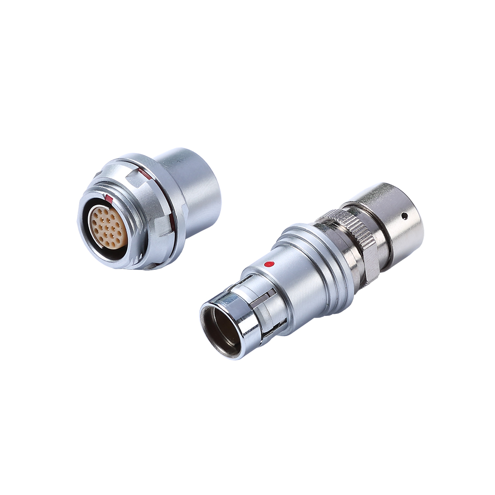
Connector materials live or die by how gracefully they wear. The usual suspects — brass, phosphor bronze, and various copper alloys — each handle repeated insertion differently. Brass starts cheap but loses its spring force after a few hundred cycles, leaving you with intermittent connections that no amount of contact cleaner will fix. Phosphor bronze holds tension longer, yet even it creeps toward failure when mating cycles climb into the thousands. The real differentiator shows up in specialty beryllium copper and high-performance stainless steels, where the material's fatigue limit sits comfortably above the mechanical stress of every plug and unplug.
What gets overlooked is how plating interacts with the base metal over time. A thick gold flash might look great on day one, but if the underlying alloy can't retain its shape, the plating cracks and flakes, exposing base metal that oxidizes within weeks. Materials that survive high mating cycles combine two properties: a base alloy with excellent stress relaxation resistance, and a plating system designed to deform with the contact rather than against it. Palladium-nickel under gold, or selective hard gold over nickel, consistently outperforms standard gold over bare copper, especially in environments where hot plugging happens before the connector has cooled.
Field data from industrial automation and aerospace tells the same story: connectors rated for ten thousand cycles fail predictably when the material was chosen on price alone, while those specified for one hundred thousand cycles often keep working well past spec because the alloy and plating were treated as a system. The lesson isn't to always buy the most expensive contact material. It's to match the expected mating lifetime to the actual fatigue behavior of the material pair, not just the datasheet's static conductivity numbers. Once you see a micrograph of a worn contact, the difference between a reliable material and a cheap one stops being abstract.
Reading Supplier Test Reports Without the Hype
When you first open a supplier test report, skip the highlighted percentages and phrases like industry-leading or best-in-class. What actually matters is buried a few lines down: the test conditions, the sample size, and whether any outliers were quietly removed. Too many reports showcase a single favorable run while tucking the failed batches into a footnote. Learn to read the sections that are visually de-emphasized, such as thermal cycling results or long-term aging data. Those numbers usually tell you more than the headline performance ever will.
A common blind spot is whether the test method matches your real operating environment. A supplier can produce beautiful data under perfectly controlled lab conditions, but your production floor has humidity swings, voltage fluctuations, and operators who don't follow protocols to the letter. Ask for the raw data set, the calibration records for the test equipment, and whether they would allow an independent lab to repeat the tests. If they hesitate on any of these, that hesitation is itself a piece of data worth weighing.
Finally, be wary of reports that hide behind dense charts and jargon. A trustworthy test report should let you grasp the key conclusion within a few minutes of reading. If you find yourself flipping back and forth trying to understand what a graph is supposed to prove, the problem is probably not your reading comprehension. The report may be designed to obscure rather than inform. Hold on to your skepticism, but don't let it turn into blanket distrust. Some data in the report will survive scrutiny, and those are the numbers you can actually use.
Contact Design for Constant Flex and Vibration
Constant flex applications expose contacts to repeated bending, micro-motion, and cyclic stress that ordinary connector geometries cannot survive. The contact design must distribute mechanical strain across a controlled flex zone rather than concentrating it at the crimp or solder joint. Materials with high fatigue resistance, such as beryllium copper or select phosphor bronze alloys, are often formed with a tapered cross-section that smoothly transitions stiffness from the rigid termination area into the flexible beam. This approach lowers peak stress at any single point and prevents the classic failure mode of work hardening followed by fracture.
Beyond material selection, the contact shape itself determines how vibration energy is absorbed. A dual-beam or split-tine configuration offers redundant current paths and dampens harmonic oscillation better than a single solid beam. In high-vibration environments, designers also add a slight preload or wiping action at the mating interface, so that micromotion does not lead to fretting corrosion. The contact blade may be formed with a curved radius that maintains normal force even as the mating pin shifts, keeping resistance stable over millions of cycles.
Termination geometry plays an equally important role. A well-designed flex contact includes a strain-relief feature near the wire entry, often a formed bellmouth or a series of gradually widening ribs, to prevent the conductor from bending at a sharp edge. For flat flexible circuits, the contact tail is sometimes made wider and thinner with rounded corners, which reduces stress risers during dynamic flexing. By treating the contact as a complete mechanical system rather than a static conductor, engineers achieve reliable signal integrity under constant motion and vibration.
Sealing Choices That Survive Dust, Oil, and Washdowns
Dust and washdown spray rarely kill a seal at the first contact, but they do expose weak lip geometry. A seal with a narrow, knife-like contact line may look precise on a data sheet, yet in service it traps fine particles and gets lifted by high-pressure water. The more durable choice uses a broad contact band plus a secondary exclusion lip that pushes debris outward while keeping the oil film intact.
Material selection works best when it matches the specific failure mode rather than a generic rating. FKM handles hot oil and many cleaners, polyurethane resists abrasive dust and cuts, and PTFE survives dry starts but demands a smooth shaft finish. In washdown zones, a stainless steel case and an EPDM sealing seat prevent corrosion from undermining the installation, while an outer scraper paired with an inner radial lip gives tighter protection than any single lip can.
Beyond the seal itself, pressure bursts from washdown spray often force moisture past an otherwise good lip because air can escape only one way. Adding a vented labyrinth, a flinger, or a drainage path ahead of the seal changes that behavior. The goal is not just a higher IP rating; it is an arrangement that sheds water during cleaning and keeps dust out during dry operation without starving the bearing of grease.
Spotting Suppliers Who Understand Field Conditions
A polished catalog or a slick website rarely reveals how a supplier performs when the ground turns to mud and the schedule slips by a week. The ones worth keeping are those who ask about soil type, weather windows, and local labor habits before quoting a single number. You can hear the difference in a first conversation: they talk about what can go wrong, not just what they plan to deliver.
Look for evidence of lived experience rather than marketing language. A supplier who has actually worked in remote or rough environments will mention details like equipment that survives dust, packaging that holds up in humidity, or contingency stock placed closer to the site. Their questions tend to be more specific — about access roads, power availability, and how crews handle downtime — because they know those variables shape the real cost and timing.
One practical way to test this is to present a small but plausible field problem and watch the reaction. A supplier with field sense will start working through options immediately, even if it means less profit on that particular order. That unguarded, problem-solving reflex is far more telling than any certificate or past-project list.
FAQ
Look past the catalog specs for evidence of field testing, honest failure data, and a willingness to discuss operating limits. A supplier that asks about vibration, temperature swings, washdown exposure, and cable flex patterns is usually more useful than one that simply quotes an IP rating. Also check whether they can provide mating cycle curves under load, not just static datasheets.
The housing and contact materials set the ceiling for everything else. Glass-filled nylon works for light-duty cells, but frequent impacts or hot environments often call for metal shells or high-grade thermoplastics. Contact alloys matter just as much: beryllium copper keeps its spring force longer than standard brass, which helps prevent intermittent faults after thousands of cycles.
Every robot joint or tool change adds micro-wear to the contact surfaces. A connector rated for a few hundred cycles may handle a static cabinet but will degrade quickly on a wrist or end effector. For moving axes, look for connectors tested beyond the expected number of tool changes over the machine's life and consider designs with sacrificial or replaceable contact inserts.
Certifications help but they only tell part of the story. Look for IEC 60529 ratings for ingress protection, UL listings for safety, and shock or vibration data based on actual application profiles. If a supplier can show salt spray, thermal shock, or continuous flex test results that match your environment, that carries more weight than a generic compliance logo.
It usually comes down to selecting the contact density and locking mechanism carefully. Miniature connectors can be robust if the housing design uses a positive latch and strain relief rather than relying on the contact pins for mechanical support. Sometimes a slightly larger connector with better cable retention saves space in the long run by reducing failure diagnosis and rework.
Plating is the actual interface where signals cross, so it has a direct effect on reliability. Gold over nickel resists corrosion and works well for low-voltage signals, while tin is cheaper but can wear through faster under vibration. In mixed power and signal connectors, selective plating puts gold only on signal contacts and leaves power contacts tin-plated, which can reduce cost without hurting data integrity.
Overmolding makes sense when the connector will face repeated washdowns, constant flexing, or tight bend radii. The molded boot removes the weak point where the cable enters the backshell and seals it in one piece. Field-wired connectors still have value for prototyping or custom cable lengths, but in production robots the consistency of an overmolded assembly often prevents early failures.
Keep a short inspection checklist: check locking rings after tool changes, look for cracked backshells or shiny wear marks on contacts, and clean with the manufacturer's recommended method instead of generic solvents. It also helps to store unmated connectors with dust caps and to avoid pulling cables by the connector body when operators reposition tools.
Conclusion
Most robot connector failures begin at predictable points: the cable entry area, the shoulder behind each contact, and the plating on pins where small vibrations gradually wear through the surface. A practical Robot Connector Supplier Guide for Choosing Durable Automation Components should start there, not with polished catalog language. Look for alloys and plating stacks that hold up after the stated mating cycles without a steady rise in contact resistance. The cycle count matters, but the resistance curve matters more. A connector that stays flat through 10,000 cycles is more credible than one that peaks at 5,000 under loosely defined conditions. Ask suppliers for test reports that show ambient temperature, vibration input, and current load. If the setup is vague or only passing samples are shown, treat that as a warning sign rather than proof of quality.
Contact design is the next filter. In constant flex and vibration, split or double-beam contacts, short unsupported lengths, and properly relieved crimps prevent intermittent opens when a robot arm changes direction. Sealing requires more than an IP rating. A washdown-rated connector may still fail in a dusty cell if the gasket compound hardens, and a tightly sealed shell can trap moisture if it is not vented correctly. Reliable suppliers ask about hose pressure, oil exposure, cycle frequency, and cable routing before making a recommendation. They also tend to state what their connectors cannot handle, which is far more useful than a generic industrial label. That field-level honesty is usually the clearest sign that a supplier understands what happens after installation.
Contact Us
Contact Person: Hayley Liang
Email: [email protected]
Tel/WhatsApp: +86 13480625451
Website: https://www.reunion-china.com/